Tuesday, 31 May 2016

TPU

TPU (Tensor Processing Unit)


-->Google has said that this device is far away better than CPU,GPU,FPGA's.
-->This is far better from above devices as it uses less transistor per unit watt
-->But contrary some blogs says at same time it occupies more power
-->This is use to develop custom hardware
-->This will be attached to the Hardisk's at Google data centre
-->One can develop custom Hardware's Using these TPU access through cloud i guess.
-->Google street view and its deep mind technology Alpha Go (Chinese Game that represent human brain) works on this TPU.
--> It is 7 generation higher than More's Law
-->It is develop with an requirnment that great softwares needs beautiful hardware
-->It is discussed in I/O conference Google by CEO sundar pichai


Reference :-Google Blog

Watch Last few minutes of speech by CEO Sundar Pichai in below video


Sunday, 22 May 2016

Interfaces (I2C ,SPI, RS232)

Interfaces are the protocols that are required by the devices to interact. Some of the common Interfaces are I2C,SPI,RS232 Interface.
Among three interface SPC is fastest after that comes I2C and finally RS232 which not has any clock. Watch below video to gain practical Knowledge too about above mentioned interfaces.Arduino has inbuilt SPC,I2C interface. and  Raspberrypi has inbuilt all interfaces. 

In below Video Ben Heck
Used SPC--to interface distance sensor with arduino
Used I2C--to interface temperature sensor with arduino
Used RS232--to interface Speaker using chip which too interfaced with the chip of RS232 which finally connected to computer where command were desired words were written to hear one by user.

Watch Below Video for better Understanding.


UART

Adding UART(Universal Asynchronous Receiver Transceiver


For More Information [Click Here]

UART
--UART is the universal Asynchronous Receiver Transiver
--It is the protocol is a self-syncronizer that is without synchronous clock with host (transceiver) the data automatically sends to the receiver.

To Understand the protocol of UART you should understand following terms

SPI Interface (Serial Peripheral Interface)--It is the protocol made by motorolla .this is a 4 wire serial communication .use to transfer data from peripheral to microcontroller/microprocessor or b/w microprocessor to microprocessor

 For More Info [Click Here]

FIFO MODE(First in First Out Mode)--It is the mode that is use in

For More Info [Click Here]

For More Knowledge from eye of chip designer Visit [Click Here] (Given Text in very interesting way)

Clock

Clock is the heart of any electronics hardware device that calculates,provides delay etc.Clock is essential in every hardware that needs a repetion like generating a ramp wave in multimeter, increasing or decressing a speed of processor, It is use almost in every device.

Clock is given using crystal oscillator, cmos ic etc.

Clock can be understanded better by student and bell example in schools

In Processor Clock impacts speed in following ways

---Raising a clock

---Dividing a clock by some factor (>1 i guess) i guess---gives more no. of cycles(Combination of each tick(1) tack(0) is known as cycle)-->fasten the speed

---Multiplying a clock by some factor (>1 i guess)---gives less no. of clock cycles (I guess if multiplication factor is greater than 1.obviously ! if it is less than 1 then it would indirectly be a division ...decimal removed ..no go down ...lab ! lab!. --> ultimately in these as time period increases therefore,no of clocks come after huge huge interval -->and thus speed reduces.

there are also many other factors to increase speed of processor beside clock like

--Pipelining
--Parllelism
--Increasing Cores of CPU
--Increasing No.  of bits like make a 64 bit ......the advantage of this reflects in high end graphics games....and not much in small programs....that is by increasing number of bits you mean to increase the data rate at a fix interval of time

For Detailed Knowledge [Click Here]

Thursday, 19 May 2016

FSM


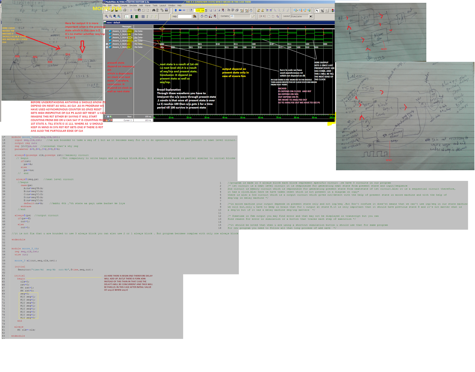
In above code you have maded two always{procedural} blocks because your “y” {past state} is a level sensitive in first always block and negedge clk is the edge triggered in your second always procedural block therefore,it is a rule you can’t write both edge triggered as well as level triggered in same sensitivity list.


Sunday, 15 May 2016

Analysis of Timing Diagram in LCD Driver

Watch from 5:37


Kinds of Signal While Analyzing a Waveforms

Differntial Pair Signalling


you can see here we mix two different kinds of waves in it .

Why we use these kinds of signal?

Ans. Because you get much higher speed with these signals


Top Channels for Electronics Engineer


1.For Techical Seminars
CCCen
2.For Projects
Ben Heck Show


PSHDL

You can do PSHDL coding in cloud itself

In PSHDL if you just write


  1. module MyFirstModule{
  2. register uint<17> counter=counter+1;
  3. }


it means the system will count at rising edge of every count

But in case you want a register to count at falling edge then in that case you have to write code as follow:-


1) Adding a Two Number using PSHDL


Do you Know How Actually Simulation is coming out on Browser? The answer to this is you have converted your code into javascript.

2) Making a Counter Using PSHDL

  1. module MyFirstModule{
  2. register uint<17> counter=counter+1;
  3. out bit led=counter(13);
  4. }
And your output will be blinking led as shown on that screen


Now you can yourself see How simple is this PSHDL